
Algorithm for resultant force of active soil pressure of excavations adjacent to underground subway stations
-
摘要: 针对有限土体主动土压力合力计算公式复杂的问题,以既有地铁车站邻域内新建基坑工程为依托,根据既有地铁车站与基坑的位置关系提出多种有限土体破坏模式,采用薄层微元法,考虑土体与结构界面摩擦作用,建立主动土压力合力计算方法。通过调整新建与既有结构空间位置关系,得到了主动土压力合力等值图,并对其开展了参数分析,提出了主动土压力简便计算方法。研究结果表明:①提出了5种有限土体破坏模式,建立了相应的主动土压力计算公式;②随着近接距离的增加,主动土压力逐渐增大;随着既有地铁车站覆土厚度的增加,靠近基坑的时候主动土压力逐渐增大,远离基坑侧的主动土压力先增大后减小最后增大;③基坑深度对主动土压力影响大,内摩擦角有影响,墙土摩擦角基本上没有影响;④给出了有限土体主动土压力合力空间位置关系系数建议取值情况。通过以上研究,提出了一种简便的有限土体主动土压力合力计算方法,可以为近接工程设计与施工提供参考。Abstract: Aiming at the problem of complex formula for calculating the resultant force of active soil pressure of limited soil, based on the newly built excavations in the vicinity of subway stations, multiple limited soil failure modes are proposed based on the positional relationship between the existing subway stations and the excavations. The thin-layer microelement method is used to consider the frictional effects between the soil and the structural interface, and a method for calculating the combined force of active soil pressure is established. By adjusting the spatial position relationship between the newly built and existing structures, an active soil pressure contour map is obtained, and the parameter analysis is conducted. Furthermore, a simple calculation method for active soil pressure is put forward. The research results indicate that: (1) Five finite soil failure modes are proposed, and the corresponding formulas for calculating the active soil pressure are established. (2) As the proximity distance increases, the active soil pressure gradually increases. As the thickness of the existing subway station cover increases, the active soil pressure gradually increases when approaching the excavation, and the active soil pressure on the side far from the excavation pit first increases, then decreases, and finally increases. (3) The depth of the excavation has a significant impact on the active soil pressure, the internal friction angle has an impact on the active soil pressure, and the wall-soil friction angle has basically no effect on the active soil pressure. (4) The value of the spatial position relationship coefficient of the combined force of active soil pressure is given. Through the above research, a simple method for the combined force of active pressure of limited soil is proposed to provide reference for the design and construction of adjacent projects.
-
Keywords:
- excavation engineering /
- adjacent project /
- limited soil /
- active soil pressure /
- contour map
-
0. 引言
城市地下空间的开发和利用中TOD(transit-oriented development)发展模式对实现低碳城市具有重要意义[1]。地铁作为其关键媒介,出现了许多在地铁车站邻域内进行高密度开发建设,使得既有地铁车站与邻近新建基坑之间形成了有限土体[2]。当经典土压力理论计算此类情况主动土压力时,往往计算值偏大,进而使得基坑支护结构设计过于保守,造成资源的浪费。
目前,薄层微元法得到的土压力强度为非线性分布与实际更为贴切[3]。Chen等[4]对相邻挡土墙间梯形滑动体进行分区,Chen等[5]研究倒T型挡土墙邻近倾斜基岩,应宏伟等[6]采用数值方法得到多道滑移面。由于墙-土摩擦作用的存在,不少学者将土拱效应引入到薄层微元法并土拱形状进行了假设(如圆弧线[7]、悬链线[8]等)。Liu等[9]考虑了第二主应力,Hu等[10]考虑层间剪切力采用薄层单元法推导了有限土体土压力计算方法。还有学者分析有限土压力与土体位移之间的关系,徐日庆等[11]针对平动模式,Lai等[12]针对绕墙底转动模式,Yang等[13]针对绕墙顶转动模式,Hu等[2]针对柔性挡土墙鼓形模式研究非极限状态狭窄回填土的土压力计算模型。
理论分析均对滑裂面形状以及土体参数等问题进行了假设和简化处理,还有学者通过模型试验揭示有限土压力分布规律。Frydman等[14]、Take等[15]采用离心模型试验分别研究了狭窄宽度下挡土墙的主动土压力和静止土压力。Xu等[16]、Yang等[17]分别针对平动、绕墙底转动、绕墙顶转动3种墙体运动模式下潜在破坏面形状。
综上所述,现阶段关于有限土体滑移面、土压力计算研究比较充分,关于有限土体的等值图需要开展进一步的研究。本文针对既有地铁车站邻域内新建基坑情况,基于土体平面滑移假定,根据新建基坑与既有地铁车站位置关系,提出多种土体破坏模式,采用薄层微元法,建立有限土体土压力计算方法,并根据基坑与地铁车站不同的位置关系得到了有限土体土压力合力等值图,创建了有限土体土压力合力简化计算方法。通过以上研究,以期提出既有地下结构近接基坑有限土体土压力合理预测方法,为近接增建基坑支护结构设计提供依据。
1. 有限土体主动土压力算法
1.1 土体破坏模式
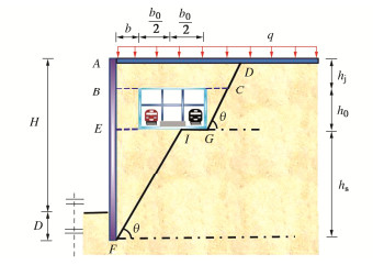
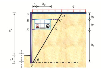
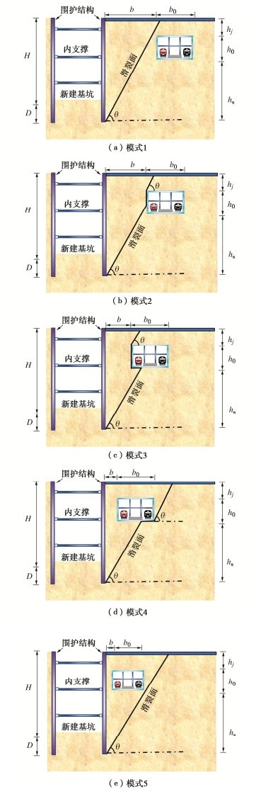
近接增建基坑工程,既有结构的存在会对基坑施工中滑移面性状产生影响。根据近接基坑土体滑移面与既有地下结构位置关系,提出5种土体破坏模式(见图 1)。模式1为既有地下结构在基坑开挖引起的滑移面外侧。模式2为基坑开挖引起的滑移面与既有地下结构边墙相接的情况。模式3为基坑开挖引起的滑移面与近基坑侧既有地下结构底板相接的情况。模式4为基坑开挖引起的滑移面与远基坑侧既有地下结构底板相接的情况。模式5为地铁车站基坑开挖引起的滑移面内侧的情况。
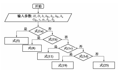
图1中,H为基坑深度,D为围护结构嵌固深度,b为基坑近接既有结构有限土体宽度(近接距离),b0为既有结构宽度,hj为覆土厚度,h0为既有结构高度,hs为围护结构底部与既有结构底板的距离。5种破坏模式下的基坑与既有地下结构位置关系式如下:
b⩾ (1a) \frac{h_{\mathrm{s}}}{\tan \left(45^{\circ}+\varphi / 2\right)} \leqslant b \leqslant \frac{\left(h_{\mathrm{s}}+h_0\right)}{\tan \left(45^{\circ}+\varphi / 2\right)}\;\;, (1b) \frac{h_{\mathrm{s}}}{\tan \left(45^{\circ}+\varphi / 2\right)}-\frac{b_0}{2} \leqslant b \leqslant \frac{h_{\mathrm{s}}}{\tan \left(45^{\circ}+\varphi / 2\right)}\;\;, (1c) \frac{h_{\mathrm{s}}}{\tan \left(45^{\circ}+\varphi / 2\right)}-b_0 \leqslant b \leqslant \frac{h_{\mathrm{s}}}{\tan \left(45^{\circ}+\varphi / 2\right)}-\frac{b_0}{2}\;\;, (1d) 0<b \leqslant \frac{h_{\mathrm{s}}}{\tan \left(45^{\circ}+\varphi / 2\right)}-b_0 \quad \text { 。 } (1e) 1.2 土体破坏模式1~3
已有研究结果给出了土体破坏模式1~3情况下的计算公式[20],下文直接给出计算公式。
模式1的土压力强度分布公式为
{\sigma _{x1}}{\text{ = }}{k_{\text{a}}}\left[ {m{{(H + D - z)}^{{a_1}}} + \frac{{\gamma (H + D - z)}}{{{a_1} - 1}}} \right]\; 。 (2) 式中,a1和m分别为
{a_1} = {k_{\text{a}}}\tan {\delta _1}\tan \theta + \frac{{{k_{\text{a}}}{{\tan }^2}\theta {\text{tan}}\varphi }}{{(tan\theta - \tan \varphi )}} + \frac{{{k_{\text{a}}}\tan \theta }}{{(tan\theta - \tan \varphi )}} - 1 \text{,} (3) m{\text{ = }}\left[ {q - \frac{{\gamma (H + D)}}{{{a_1} - 1}}} \right]{(H + D)^{ - {a_1}}}\; 。 (4) 模式1的土压力的合力为
{E_{\text{a}}} = \int_0^{H + D} {{\sigma _{x1}}} dz = \frac{{{k_{\text{a}}}\gamma {{(H + D)}^2}}}{{2({a_1} - 1)}} + \frac{{{k_{\text{a}}}m{{(H + D)}^{{a_1} + 1}}}}{{{a_1} + 1}} 。 (5) 模式2的土压力强度分布公式为
{\sigma }_{x1}\text{=}{k}_{\text{a}}\left({m}_{1}{(b\mathrm{tan}\theta +{h}_{\text{j}}-z)}^{{a}_{1}}+\frac{\gamma (b\mathrm{tan}\theta +{h}_{\text{j}}-z)}{{a}_{1}-1}\right)\text{ }\text{,} (6a) {\sigma }_{x1}={k}_{\text{a}}\left({m}_{2}{\text{e}}^{-{a}_{2}z}+\frac{\gamma }{{a}_{2}}\right)\text{ }\text{,} (6b) {\sigma }_{x1}={k}_{\text{a}}\left[{m}_{3}{(H+D-z)}^{{a}_{1}}+\frac{\gamma (H+D-z)}{{a}_{1}-1}\right]\text{ }。 (6c) 式中:m1,m2,m3,a2分别为
{m_1} = \left[ {q - \frac{{\gamma (b\tan \theta + {h_{\text{j}}})}}{{{a_1} - 1}}} \right]{(b\tan \theta + {h_{\text{j}}})^{ - {a_1}}}\;\; \text{,} (7a) {m_2} = \left\{ {\left[ {{m_1}{{(b\tan \theta )}^{{a_1}}} + \frac{{\gamma b\tan \theta }}{{{a_1} - 1}}} \right] - \frac{\gamma }{{{a_2}}}} \right\}{{\text{e}}^{{a_2}{h_j}}} \;\text{,} (7b) {m_3} = \frac{{{m_2}{{\text{e}}^{ - {a_2}(D + H - b\tan \theta )}} + \frac{\gamma }{{{a_2}}} - \frac{{\gamma b\tan \theta }}{{{a_1} - 1}}}}{{{{(b\tan \theta )}^{{a_1}}}}} \;\text{,} (7c) {a_2}{\text{ = }}\frac{{{k_{\text{a}}}}}{b}(\tan {\delta _1} + \tan {\delta _2}) \;。 (7d) 模式2土压力的合力为
\begin{array}{l} E_{\mathrm{a}}=k_{\mathrm{a}}\left[\frac{\gamma\left[\left(h_{\mathrm{j}}+b \tan \theta\right)^2\right]}{2\left(a_1-1\right)}+\right. \\ \frac{m_1\left(h_{\mathrm{j}}+b \tan \theta\right)^{a_1+1}+\left(m_3-m_1\right)(b \tan \theta)^{a_1+1}}{a_1+1}+ \\ \left.\frac{\gamma\left(h_0+h_{\mathrm{s}}-b \tan \theta\right)+m_2\left(\mathrm{e}^{-a_2 h_{\mathrm{j}}}-\mathrm{e}^{-a_2(H+D-b \tan \theta)}\right)}{a_2}\right] 。 \end{array} (8) 模式3的土压力强度分布公式为
{\sigma _{x1}} = {k_{\text{a}}}\left[ {{m_1}{{(b\tan \theta + {h_{\text{j}}} - z)}^{{a_1}}} + \frac{{\gamma (b\tan \theta + {h_{\text{j}}} - z)}}{{{a_1} - 1}}} \right] \text{,} (9a) {\sigma _{x1}} = {k_{\text{a}}}\left( {{m_2}{{\text{e}}^{ - {a_2}z}} + \frac{\gamma }{{{a_2}}}} \right) \;\text{,} (9b) {\sigma _{x1}} = {k_{\text{a}}}\left[ {{m_4}{{(H + D - z)}^{{a_1}}} + \frac{{\gamma (H + D - z)}}{{{a_1} - 1}}} \right] \text{,} (9c) 式中:m4为
{m_4} = \frac{{\left( {{m_2}{{\text{e}}^{ - {a_2}({h_0} + {h_{\text{j}}})}} + \frac{\gamma }{{{a_2}}}} \right)\frac{{b\tan \theta }}{{{h_{\text{s}}}}} - \frac{{\gamma (H + D - {h_0} - {h_{\text{j}}})}}{{{a_1} - 1}}}}{{{{(H + D - {h_0} - {h_{\text{j}}})}^{{a_1}}}}} 。 (10) 模式3土压力的合力为
\begin{array}{c} E_{\mathrm{a}}=k_{\mathrm{a}}\left[\frac{\gamma\left[\left(h_{\mathrm{j}}+b \tan \theta\right)^2+h_{\mathrm{s}}^2-(b \tan \theta)^2\right]}{2\left(a_1-1\right)}+\right. \\ \frac{m_1\left[\left(h_{\mathrm{j}}+b \tan \theta\right)^{a_1+1}-(b \tan \theta)^{a_1+1}\right]+m_4 h_{\mathrm{s}}^{a_1+1}}{a_1+1}+ \\ \left.\frac{\gamma h_0+m_2\left(\mathrm{e}^{-a_2 h_{\mathrm{j}}}-\mathrm{e}^{-a_2\left(h_0+h_{\mathrm{j}}\right)}\right)}{a_2}\right] 。 \end{array} (11) 故本文只针对破坏模式4,5展开推导。
1.3 土体破坏模式4
根据滑移面与既有车站位置关系,土体产生了沿图 2中的FIGD面滑动。为了便于对滑移体AFIGD进行力学分析,将其分为ABCD、BEGC、EFI三部分。滑移体EFI向下滑动,接触面GI上既有车站与土体不存在相互作用。
地铁车站自重为G0,为了简化计算将模式4中滑移体BEGC等效重度为
{\gamma }_{\text{D}}\text{=}\frac{{G}_{0}\text{+}\gamma \left(b{h}_{0}\text{+}\frac{{h}_{0}^{2}}{2\mathrm{tan}\theta }\right)}{{b}_{0}{h}_{0}+b{h}_{0}\text{+}\frac{{h}_{0}^{2}}{2\mathrm{tan}\theta }}=\frac{2\mathrm{tan}\theta {G}_{0}\text{+}\gamma (2\mathrm{tan}\theta b{h}_{0}\text{+}{h}_{0}^{2})}{2\mathrm{tan}\theta {b}_{0}{h}_{0}+2\mathrm{tan}\theta b{h}_{0}\text{+}{h}_{0}^{2}}。 (12) (1)滑移体ABCD
对微元水平与竖直方向建立力学平衡方程,其通解形式同式(2),即
\begin{array}{l} \sigma_{x 1}=k_{\mathrm{a}}\left[m_5\left[\left(b+b_0\right) \tan \theta+h_0+h_{\mathrm{j}}-z\right]^{a_1}+\right. \\ \;\;\;\;\;\;\;\;\;\;\;\;\left.\frac{\gamma\left[\left(b+b_0\right) \tan \theta+h_0+h_{\mathrm{j}}-z\right]}{a_1-1}\right]\;\;。 \end{array} (13) 式(13)中, {m_5} 为待定系数,当z=0时, {\sigma _z} =q,代入式(13)中,得
{m}_{5}\text{=}\left[q-\frac{\gamma [(b+{b}_{0})\mathrm{tan}\theta +{h}_{0}+{h}_{\text{j}}]}{{a}_{1}-1}\right]{[(b+{b}_{0})\mathrm{tan}\theta +{h}_{0}+{h}_{\text{j}}]}^{-{a}_{1}}。 (14) (2)滑移体BEGC
对微元水平与竖直方向建立力学平衡方程,其通解形式同式(2),即
\begin{array}{l} \sigma_{x 1}=k_{\mathrm{a}}\left[\frac{\gamma_{\mathrm{D}}\left[\left(b+b_0\right) \tan \theta+h_0+h_{\mathrm{j}}-z\right]}{a_1-1}+\right. \\ \;\;\;\;\;\;\;\;\;\;\;\;\;\;\;\;\;\;\;\;\left.m_6\left[\left(b+b_0\right) \tan \theta+h_0+h_{\mathrm{j}}-z\right]^{a_1}\right] 。 \end{array} (15) 当z=hj时,将式(13)代入式(15)中得到
\begin{array}{l}m_6=\left[m_5\left[\left(b+b_0\right) \tan \theta+h_0\right]^{a_1}+\frac{\left(\gamma-\gamma_{\mathrm{D}}\right)\left[\left(b+b_0\right) \tan \theta+h_0\right]}{a_1-1}\right] .\\\;\;\;\;\;\;\;\;\;\;\;\;\;\;\;\;\;\;\;\;\;\;\;\;\;\;\;\;\;\;\;{[(b + {b_0})\tan \theta + {h_0}]^{ - {a_1}}} 。\end{array} (16) (3)滑移体EFI
对微元水平与竖直方向建立力学平衡方程,其通解形式同式(2),即
{\sigma _{x1}} = {k_{\text{a}}}\left[ {{m_7}{{(H + D - z)}^{{a_1}}} + \frac{{\gamma (H + D - z)}}{{{a_1} - 1}}} \right] 。 (17) 当z=hj+h0时,将式(15)代入式(17)中得到
{m_7} = {h_{\text{s}}}^{ - {a_1}}\left[ {[{m_6}{{(b\tan \theta + {b_0}\tan \theta )}^{{a_1}}} + \frac{{{\gamma _{\text{D}}}(b + {b_0})\tan \theta }}{{{a_1} - 1}}]\frac{{(b + {b_0})\tan \theta }}{{{h_{\text{s}}}}} - \frac{{\gamma {h_{\text{s}}}}}{{{a_1} - 1}}} \right] (18) 模式4土压力合力为
\begin{array}{l} {E_{\text{a}}} = {k_{\text{a}}}\left[ {\frac{{\gamma {h_s}^2 + {\gamma _D}{{[{h_{\text{j}}} + {h_0} + (b + {b_0})\tan \theta ]}^2} - (\gamma + {\gamma _D}){{[{h_0} + (b + {b_0})\tan \theta ]}^2}}}{{2({a_1} - 1)}} + } \right. \hfill \\ \;\;\;\;\;\;\;\;\frac{{{m_5}{{[{h_{\text{j}}} + {h_0} + (b + {b_0})\tan \theta ]}^{{a_1} + 1}} - {m_6}{{[(b + {b_0})\tan \theta ]}^{{a_1} + 1}}}}{{{a_1} + 1}} + \hfill \\ \;\;\;\;\;\;\;\;\left. {\frac{{({m_6} - {m_5}){{[{h_0} + (b + {b_0})\tan \theta ]}^{{a_1} + 1}} + {m_7}{h_{\text{s}}}^{{a_1} + 1}}}{{{a_1} + 1}}} \right] 。 \end{array} (19) 1.4 土体破坏模式5
根据滑移面与既有车站位置关系,土体产生了沿图 3中的FGCD面滑动。为了便于对不规则滑移体AFD进行力学分析,将其分为ABCD、BEGC、EFG三部分。
其中滑移体BEGC等效重度为
{\gamma _{{\text{D1}}}}{\text{ = }}\frac{{2\tan \theta {G_0}{\text{ + }}\gamma {h_0}(2{h_{\text{s}}} + {h_0} - 2{b_0}\tan \theta )}}{{2{h_0}{h_{\text{s}}} + h_{_0}^2}} 。 (20) (1)滑移体ABCD
滑移体ABCD力学分析过程完全同模型1,参见式(2)。
(2)滑移体BEGC
对微元水平与竖直方向建立力学平衡方程,其通解形式同式(2),即
{\sigma _{x1}} = {k_{\text{a}}}\left[ {{m_8}{{(H + D - z)}^{{a_1}}} + \frac{{{\gamma _{{\text{D1}}}}(H + D - z)}}{{{a_1} - 1}}} \right] 。 (21) 当z=hj时,将式(2)代入式(21),得到
{m_8}{\text{ = }}\left[ {m{{({h_0} + {h_{\text{s}}})}^{{a_1}}} + \frac{{(\gamma - {\gamma _{{\text{D1}}}})({h_0} + {h_{\text{s}}})}}{{{a_1} - 1}}} \right]{({h_0} + {h_{\text{s}}})^{ - {a_1}}} 。 (22) (3)滑移体EFG
对微元水平与竖直方向建立力学平衡方程,其通解形式同式(2),即
{\sigma _{x1}} = {k_{\text{a}}}\left[ {{m_9}{{(H + D - z)}^{{a_1}}} + \frac{{\gamma (H + D - z)}}{{{a_1} - 1}}} \right] 。 (23) 当z=hj+h0时,将式(21)代入式(23),得到
{m_9} = \left[ {{m_8}{h_{\text{s}}}^{{a_1}} + \frac{{({\gamma _{{\text{D1}}}} - \gamma ){h_{\text{s}}}}}{{{a_1} - 1}}} \right]{h_{\text{s}}}^{ - {a_1}} 。 (24) 模式5土压力的合力为
{E_{\text{a}}} = {k_{\text{a}}}\left[ {\frac{{\gamma [{h_{\text{s}}}^{\text{2}} + {{(H + D)}^2} - {{({h_0} + {h_{\text{s}}})}^2}] + {\gamma _{D1}}[{{({h_0} + {h_{\text{s}}})}^2} - {h_{\text{s}}}^2]}}{{2({a_1} - 1)}}} \right. + \\ \frac{({m}_{9}-{m}_{8}){({h}_{0}+{h}_{\text{s}})}^{{a}_{1}+1}-{m}_{8}{(H+D)}^{{a}_{1}+1}+({m}_{10}-{m}_{9}){h}_{\text{s}}^{{a}_{1}+1}}{{a}_{1}+1}]。 (25) 1.5 两种破坏模式公式一致性验证
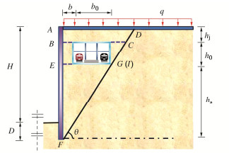
当有限土体的滑裂面与既有地铁车站相交于图 2中G点时(见图 4),该工况均为土体破坏模式4,5的临界状态。根据几何关系可知
b=h_{\mathrm{s}} / \tan \left(45^{\circ}+\varphi / 2\right)-b_0\;\; 。 (26) 随后,将式(26)代入式(13),(15)与(17)中,得到
\begin{array}{l}{\sigma }_{x1}={k}_{\text{a}}\left[{m}_{5}{(H+D-z)}^{{a}_{2}}+\frac{\gamma (H+D-z)}{{a}_{2}-1}\right]\;\;\text{ (}AB段\text{)}\text{,}\\ {\sigma }_{x1}={k}_{\text{a}}\left[{m}_{6}{(H+D-z)}^{{a}_{2}}+\frac{{\gamma }_{\text{D}}(H+D-z)}{{a}_{2}-1}\right]\text{ (}BE段\text{)}\text{,}\\ {\sigma }_{x1}={k}_{\text{a}}\left[{m}_{7}{(H+D-z)}^{{a}_{2}}+\frac{\gamma (H+D-z)}{{a}_{2}-1}\right]\;\;\text{ (}EF段\text{)}\text{,}\text{ }\\ {m}_{5}=\left[q-\frac{\gamma (H+D)}{{a}_{2}-1}\right](H+D)^{-a_2}\text{,}\\ {m}_{6}=\left[{m}_{5}{({h}_{\text{s}}+{h}_{0})}^{{a}_{2}}+\frac{(\gamma -{\gamma }_{\text{D}})({h}_{\text{s}}+{h}_{0})}{{a}_{2}-1}\right]\left(h_{\mathrm{s}}+h_0\right)^{-a_2}\text{,}\\ \;\;\;\;\;\;\;\;\;\;\;\;\;\;\;\;\;{m}_{7}=\left[{m}_{6}{h}_{\text{s}}{}^{{a}_{2}}+\frac{({\gamma }_{\text{D}}-\gamma ){h}_{\text{s}}}{{a}_{1}-1}\right]{h}_{\text{s}}{}^{-{a}_{2}}。 \end{array} (27) 将式(26)代入式(2),(21),(23)中,得到
\begin{array}{l}{\sigma }_{x1}={k}_{\text{a}}\left[m{(H+D-z)}^{{a}_{2}}+\frac{\gamma (H+D-z)}{{a}_{2}-1}\right]\;\;\;\;\text{ (}AB段\text{)}\text{,}\\ {\sigma }_{x1}={k}_{\text{a}}\left[{m}_{8}{(H+D-z)}^{{a}_{2}}+\frac{{\gamma }_{\text{D1}}(H+D-z)}{{a}_{2}-1}\right]\text{ (}BE段\text{)}\text{,}\\ {\sigma }_{x1}={k}_{\text{a}}\left[{m}_{9}{(H+D-z)}^{{a}_{2}}+\frac{\gamma (H+D-z)}{{a}_{2}-1}\right]\;\;\text{ (}EF段\text{)}\text{,}\\ m=\left[q-\frac{\gamma (H+D)}{{a}_{2}-1}\right](H+D)^{-a_2}\text{,}\\ {m}_{8}\text{=}\left[m{({h}_{0}+{h}_{\text{s}})}^{{a}_{2}}+\frac{(\gamma -{\gamma }_{\text{D1}})({h}_{0}+{h}_{\text{s}})}{{a}_{2}-1}\right]\left(h_0+h_{\mathrm{s}}\right)^{-a_2}\text{,}\\\;\;\;\;\;\;\;\;\;\;{m}_{9}=\left[{m}_{8}{h}_{\text{s}}{}^{{a}_{2}}+\frac{({\gamma }_{\text{D1}}-\gamma ){h}_{\text{s}}}{{a}_{1}-1}\right]{h}_{\text{s}}{}^{-{a}_{2}}\text{ }。\end{array} (28) 通过以上分析,以上两种土体破坏模式下的有限土体主动土压力计算方法具有一致性。
2. 有限土体土压力等值图
2.1 概念
针对既有结构邻域内新建基坑工程,国内外诸多学者对既有结构展开了相关研究,主要以结合工程实践的数值模拟分析为主[18-19],其研究重点均集中在新建结构对既有结构的变形及受力性状影响。本章通过计算多个基坑与地铁车站相对位置下围护结构受到的土压力合力,并将土压力合力绘制成等值线用来探究既有结构对基坑围护结构影响规律。
2.2 计算流程
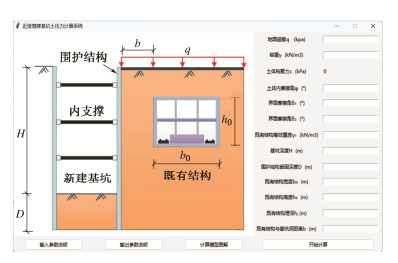
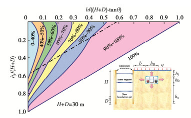
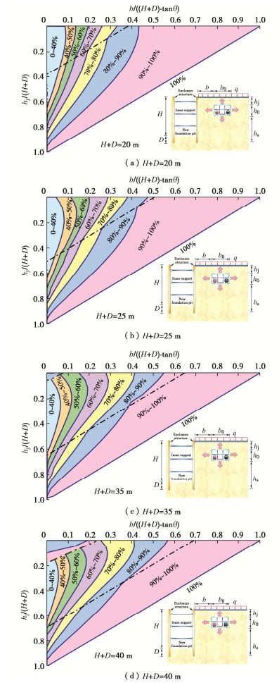
根据上文得到的土压力公式,制作了有限土压力计算程序,通过该程序可以得到任何工况下邻近地铁车站的围护结构上的土压力的合力(图 5,6)。利用该程序求得不同b,hj条件下的土压力合力,并将0.4 {E_{{\text{amax}}}} ,0.5 {E_{{\text{amax}}}} ,0.6 {E_{{\text{amax}}}} ,0.7 {E_{{\text{amax}}}} ,0.8 {E_{{\text{amax}}}} ,0.9 {E_{{\text{amax}}}} 处坐标连成线绘制成等值线图( {E_{{\text{amax}}}} 为半无限土体的土压力合力)。
2.3 计算工况
给出一算例,其参数为:地面无超载, \gamma =16.2 kN/m3,c=0 kPa,φ=35°,δ1=δ2=20°,H=25 m,D=5 m,h0=12.4 m,b0=21.2 m,通过多组工况下(不同近接距离b和不同覆土深度hj)围护结构上的土压力合力绘制等值图线(图 7)。
以半无限土体界限为标准,对横纵坐标进行参数归一化处理。等值线呈非线性分布,界限处发生突变,并随着近接距离的减少,覆土深度的增加,突变效应减小,这主要由于既有地铁车站底板处发生形成了应力释放且与滑裂面的形状有关。基坑土压力的影响区大致可简化为直角梯形形状,可用于预估基坑受到的有限土体土压力。
3. 参数分析
3.1 近接距离
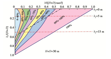
当既有地下结构覆土深度分别为0,5,10 m时,有限土体土压力合力如图 8中的红线所示。对于hj=0 m的同一条红线,表示既有地下结构覆土深度为0 m,不同近接距离下的有限土体土压力合力。
如图 8可见,同一覆土深度下,当近接距离越大,围护结构受到的土压力合力越大,且等值线间距越大,说明近接距离对土压力的敏感性随着b增大而逐渐削弱,直到b≥(hs+h0)/tanθ半无限土体不再受到影响。随着覆土深度的增加,同一等值线间距越小,说明覆土深度越大时近接距离对土压力的影响越大。
3.2 既有地铁车站覆土厚度
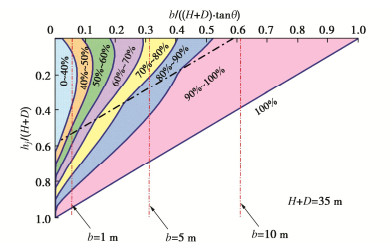
当近接距离分别为1,5,10 m时,有限土体土压力合力如图 9中的红线所示。对于b=1 m的同一条红线,表示近接距离为1 m,不同既有地下结构埋深的有限土体土压力合力。
如图 9所示,当近接距离较大时,超过5 m时,围护结构受到的土压力合力随着覆土深度增加而增大;当近接距离较小时,小于5 m时,围护结构受到的土压力合力随着覆土深度增加,先减小后增大。有限土体的面积是影响土压力大小的重要因素,当近接距离较小时,随着覆土深度的增加,有限土体的面积先减小后增大。
3.3 新建基坑深度
通过改变基坑深度,控制插入比为5∶1,基坑深度取为5种,分别为16.7,20.8,29.2,33.4 m,嵌固深度分别为3.3,4.2,5.8,6.6 m,H+D分别为20,25,35,40 m,来观察基坑深度对等值图的影响。
如图 10所示,随着围护结构高度的增加,土压力的值增长很快。当围护结构高度增加到一定程度且近接距离和覆土深度很小时,此时对应模式4,土压力突然增大。主要是由于滑裂面形状改变后使得滑动土体的面积增大。
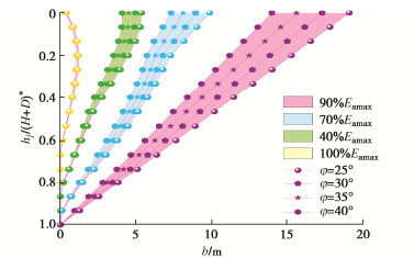
3.4 内摩擦角
选取内摩擦角分别为25°,30°,35°,40°的情况,墙土摩擦角仍按(δ1/φ=δ2/φ=4/7)比例选取,其它参数不变观察覆土深度对等值图的影响。
如图 11可见,不同合力大小对于内摩擦角的改变出现了类似等比的影响,当合力为0.4Eamax时,影响特别微弱。随着合力的增大,影响也越来越强。同时,同一位置处相同φ差值改变对土压力影响一致。当hj越大时,相同φ差值改变对土压力影响越来越小。
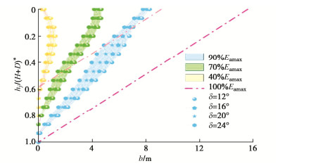
3.5 墙-土摩擦角
其它参数不变,选取墙-土摩擦角分别为12°,16°,20°,24°的情况,分析墙-土摩擦角对等值图的规律。
如图 12可见,相较于内摩擦角,墙土摩擦角对等值图的影响较小。随着界面摩擦角的减少,等值线发生类似向左的移动。
4. 简化计算方法
根据第1节给出的模式1(半无限土体)土压力计算公式,通过积分得到土压力合力:
{E}_{\text{a(}半无限\text{)}}=\frac{{k}_{\text{a}}\gamma {(H+D)}^{2}}{2({a}_{1}-1)}+\frac{{k}_{\text{a}}m{(H+D)}^{{a}_{1}+1}}{{a}_{1}+1}\text{ }。 (29) 为了简化有限土体土压力合力计算公式,在半无限土体土压力合力的基础上,乘以一个有限土体土压力合力空间位置关系系数,提出有限土体土压力合力简便计算方法:
{E}_{\text{a}}=\lambda \cdot {E}_{\text{a(}半无限\text{)}} \;\;\;。 (30) 式中, \lambda 为有限土体主动土压力合力空间位置关系系数。
以基坑围护结构为25 m(H+D=25 m),近接距离b=9 m,既有地铁车站覆土厚度为hj=9 m为例,给出 \lambda 建议取值的由来。当满足以上参数时,根据第3~4节研究结果,参考图 10(b),以上参数条件下有限土体土压力合力落在图 10(b)中70%~80%区域,取 \lambda =0.8。根据以上原理,绘制了 \lambda 建议取值表,具体见表 1~5。
表 1 H+D=20 m时空间位置关系系数 \lambda 建议值Table 1. Suggested values of coefficient of spatial position relationship when H+D=20 m(单位: m) hj b 3 5 7 9 11 13 15 ≥17 3 0.4 0.6 0.7 0.8 0.9 0.9 0.9 1 6 0.4 0.7 0.7 0.8 0.9 0.9 0.9 1 9 0.4 0.8 0.8 0.9 0.9 1 1 1 12 0.5 0.9 0.9 1 1 1 1 1 15 0.7 1 1 1 1 1 1 1 ≥18 1 1 1 1 1 1 1 1 表 2 H+D=25 m时空间位置关系系数 \lambda 建议值Table 2. Suggested values of coefficient of spatial position relationship when H+D=25 m(单位: m) hj b 3 5 7 9 11 13 15 ≥17 3 0.4 0.5 0.6 0.6 0.7 0.8 0.8 1 6 0.4 0.5 0.6 0.7 0.8 0.8 0.9 1 9 0.5 0.6 0.7 0.8 0.9 0.9 0.9 1 12 0.6 0.7 0.8 0.9 0.9 1 1 1 15 0.7 0.8 0.9 0.9 1 1 1 1 18 0.8 0.9 1 1 1 1 1 1 ≥21 1 1 1 1 1 1 1 1 表 3 H+D=30 m时空间位置关系系数 \lambda 建议值Table 3. Suggested values of coefficient of spatial position relationship when H+D=30 m(单位: m) hj b 3 7 11 15 19 23 ≥27 3 0.4 0.5 0.6 0.7 0.8 0.9 1 6 0.4 0.5 0.7 0.8 0.9 0.9 1 9 0.4 0.6 0.7 0.8 0.9 1 1 12 0.5 0.7 0.8 0.9 1 1 1 15 0.5 0.8 0.9 0.9 1 1 1 18 0.6 0.8 0.9 1 1 1 1 21 0.7 0.9 1 1 1 1 1 24 0.9 1 1 1 1 1 1 ≥27 1 1 1 1 1 1 1 表 4 H+D=35 m时空间位置关系系数 \lambda 建议值Table 4. Suggested values of coefficient of spatial position relationship when H+D=35 m(单位: m) hj b 3 7 11 15 19 23 27 31 ≥35 3 0.5 0.6 0.6 0.7 0.8 0.8 0.8 0.9 1 6 0.4 0.5 0.6 0.7 0.8 0.8 0.9 1 1 9 0.4 0.5 0.6 0.7 0.8 0.9 1 1 1 12 0.4 0.6 0.7 0.8 0.9 0.9 1 1 1 15 0.5 0.6 0.8 0.9 0.9 1 1 1 1 18 0.5 0.7 0.9 0.9 1 1 1 1 1 21 0.6 0.8 0.9 1 1 1 1 1 1 24 0.7 0.9 1 1 1 1 1 1 1 27 0.8 0.9 1 1 1 1 1 1 1 30 0.9 1 1 1 1 1 1 1 1 ≥33 1 1 1 1 1 1 1 1 1 表 5 H+D=40 m时空间位置关系系数 \lambda 建议值Table 5. Suggested values of coefficient of spatial position relationship when H+D=40 m(单位: m) hj b 3 9 15 21 27 33 39 ≥45 3 0.8 0.9 0.7 0.7 0.8 0.9 0.9 1 6 0.9 0.6 0.7 0.7 0.8 0.9 1 1 9 0.4 0.6 0.7 0.8 0.8 0.9 1 1 12 0.4 0.6 0.7 0.8 0.9 1 1 1 15 0.4 0.6 0.7 0.9 1 1 1 1 18 0.5 0.7 0.8 0.9 1 1 1 1 21 0.5 0.7 0.9 1 1 1 1 1 24 0.6 0.8 0.9 1 1 1 1 1 27 0.7 0.9 1 1 1 1 1 1 30 0.8 0.9 1 1 1 1 1 1 33 0.9 1 1 1 1 1 1 1 ≥36 1 1 1 1 1 1 1 1 5. 结论
本文针对既有车站邻域内增建基坑情况,根据基坑与既有车站位置关系,采用薄层单元法推导了土体多种破坏模式下产生的有限土压力,绘制了有限土体土压力等值图,并进行了参数分析,提出了有限土体土压力合力简便计算方法。通过以上研究,得到以下5点结论。
(1)根据基坑与既有地铁车站空间位置关系,提出了5种有限土体破坏模式,建立了相应的主动土压力计算公式。
(2)等值线呈非线性分布,界限处发生突变,并随着近接距离的减少,覆土深度的增加,突变效应减小,这主要由于既有地铁车站底板处发生形成了应力释放且与滑裂面的形状有关。
(3)随着近接距离的增加,主动土压力逐渐增大;随着既有地铁车站覆土厚度的增加,靠近基坑的时候主动土压力逐渐增大,远离基坑侧的主动土压力先增大后减小最后增大。
(4)基坑深度对主动土压力影响大,内摩擦角对主动土压力有影响,墙土摩擦角对主动土压力基本上没有影响。
(5)建立了有限土体主动土压力合力简便计算方法,给出了有限土体主动土压力合力空间位置关系系数建议值。
-
表 1 H+D=20 m时空间位置关系系数建议值
Table 1 Suggested values of coefficient of spatial position relationship when H+D=20 m
(单位: m) hj b 3 5 7 9 11 13 15 ≥17 3 0.4 0.6 0.7 0.8 0.9 0.9 0.9 1 6 0.4 0.7 0.7 0.8 0.9 0.9 0.9 1 9 0.4 0.8 0.8 0.9 0.9 1 1 1 12 0.5 0.9 0.9 1 1 1 1 1 15 0.7 1 1 1 1 1 1 1 ≥18 1 1 1 1 1 1 1 1  下载: 导出CSV
表 2 H+D=25 m时空间位置关系系数建议值
Table 2 Suggested values of coefficient of spatial position relationship when H+D=25 m
(单位: m) hj b 3 5 7 9 11 13 15 ≥17 3 0.4 0.5 0.6 0.6 0.7 0.8 0.8 1 6 0.4 0.5 0.6 0.7 0.8 0.8 0.9 1 9 0.5 0.6 0.7 0.8 0.9 0.9 0.9 1 12 0.6 0.7 0.8 0.9 0.9 1 1 1 15 0.7 0.8 0.9 0.9 1 1 1 1 18 0.8 0.9 1 1 1 1 1 1 ≥21 1 1 1 1 1 1 1 1
下载: 导出CSV
表 3 H+D=30 m时空间位置关系系数建议值
Table 3 Suggested values of coefficient of spatial position relationship when H+D=30 m
(单位: m) hj b 3 7 11 15 19 23 ≥27 3 0.4 0.5 0.6 0.7 0.8 0.9 1 6 0.4 0.5 0.7 0.8 0.9 0.9 1 9 0.4 0.6 0.7 0.8 0.9 1 1 12 0.5 0.7 0.8 0.9 1 1 1 15 0.5 0.8 0.9 0.9 1 1 1 18 0.6 0.8 0.9 1 1 1 1 21 0.7 0.9 1 1 1 1 1 24 0.9 1 1 1 1 1 1 ≥27 1 1 1 1 1 1 1
下载: 导出CSV
表 4 H+D=35 m时空间位置关系系数建议值
Table 4 Suggested values of coefficient of spatial position relationship when H+D=35 m
(单位: m) hj b 3 7 11 15 19 23 27 31 ≥35 3 0.5 0.6 0.6 0.7 0.8 0.8 0.8 0.9 1 6 0.4 0.5 0.6 0.7 0.8 0.8 0.9 1 1 9 0.4 0.5 0.6 0.7 0.8 0.9 1 1 1 12 0.4 0.6 0.7 0.8 0.9 0.9 1 1 1 15 0.5 0.6 0.8 0.9 0.9 1 1 1 1 18 0.5 0.7 0.9 0.9 1 1 1 1 1 21 0.6 0.8 0.9 1 1 1 1 1 1 24 0.7 0.9 1 1 1 1 1 1 1 27 0.8 0.9 1 1 1 1 1 1 1 30 0.9 1 1 1 1 1 1 1 1 ≥33 1 1 1 1 1 1 1 1 1
下载: 导出CSV
表 5 H+D=40 m时空间位置关系系数建议值
Table 5 Suggested values of coefficient of spatial position relationship when H+D=40 m
(单位: m) hj b 3 9 15 21 27 33 39 ≥45 3 0.8 0.9 0.7 0.7 0.8 0.9 0.9 1 6 0.9 0.6 0.7 0.7 0.8 0.9 1 1 9 0.4 0.6 0.7 0.8 0.8 0.9 1 1 12 0.4 0.6 0.7 0.8 0.9 1 1 1 15 0.4 0.6 0.7 0.9 1 1 1 1 18 0.5 0.7 0.8 0.9 1 1 1 1 21 0.5 0.7 0.9 1 1 1 1 1 24 0.6 0.8 0.9 1 1 1 1 1 27 0.7 0.9 1 1 1 1 1 1 30 0.8 0.9 1 1 1 1 1 1 33 0.9 1 1 1 1 1 1 1 ≥36 1 1 1 1 1 1 1 1
下载: 导出CSV
-
[1] ALI L, NAWAZ A, IQBAL S, et al. Dynamics of transit oriented development, role of greenhouse gases and urban environment: a study for management and policy[J]. Sustainability, 2021, 13(5): 2536. doi: 10.3390/su13052536
[2] HU W D, ZHU X N, ZENG Y Q, et al. Active earth pressure against flexible retaining wall for finite soils under the drum deformation mode[J]. Scientific Reports, 2022, 12(1): 497. doi: 10.1038/s41598-021-04411-4
[3] FAN C C, FANG Y S. Numerical solution of active earth pressures on rigid retaining walls built near rock faces[J]. Computers and Geotechnics, 2010, 37(7/8): 1023-1029.
[4] CHEN J J, LI M G, WANG J H. Active earth pressure against rigid retaining walls subjected to confined cohesionless soil[J]. International Journal of Geomechanics, 2017, 17(6): 06016041. doi: 10.1061/(ASCE)GM.1943-5622.0000855
[5] CHEN F Q, CHEN H B, XU L, et al. Seismic pseudo-static active earth pressure of narrow granular backfill against an inverted T-type retaining wall under translational mode[J]. Soil Dynamics and Earthquake Engineering, 2022, 152: 107018. doi: 10.1016/j.soildyn.2021.107018
[6] 应宏伟, 黄东, 谢新宇. 考虑邻近地下室外墙侧压力影响的平动模式挡土墙主动土压力研究[J]. 岩石力学与工程学报, 2011, 30(增刊1): 2970-2978. https://www.cnki.com.cn/Article/CJFDTOTAL-YSLX2011S1050.htm YING Hongwei, HUANG Dong, XIE Xinyu. Study of active earth pressure on retaining wall subject to translation mode considering lateral pressure on adjacent existing basement exterior wall[J]. Chinese Journal of Rock Mechanics and Engineering, 2011, 30(S1): 2970-2978. (in Chinese) https://www.cnki.com.cn/Article/CJFDTOTAL-YSLX2011S1050.htm
[7] CHEN F Q, LIN Y J, YANG J T, et al. Passive earth pressure of narrow cohesionless backfill against rigid retaining walls rotating about the base[J]. International Journal of Geomechanics, 2021, 21(1): 06020036. doi: 10.1061/(ASCE)GM.1943-5622.0001889
[8] HANDY R L. The arch in soil arching[J]. Journal of Geotechnical Engineering, 1985, 111(3): 302-318. doi: 10.1061/(ASCE)0733-9410(1985)111:3(302)
[9] LIU H, KONG D Z. Active earth pressure of finite width soil considering intermediate principal stress and soil arching effects[J]. International Journal of Geomechanics, 2022, 22(3): 04021294. doi: 10.1061/(ASCE)GM.1943-5622.0002298
[10] HU W D, ZHU X N, LIU X H, et al. Active earth pressure against cantilever retaining wall adjacent to existing basement exterior wall[J]. International Journal of Geomechanics, 2020, 20(11): 04020207. doi: 10.1061/(ASCE)GM.1943-5622.0001853
[11] 徐日庆, 徐叶斌, 程康, 等. 有限土体下考虑土拱效应的非极限主动土压力解[J]. 岩土工程学报, 2020, 42(2): 362-371. doi: 10.11779/CJGE202002018 XU Riqing, XU Yebin, CHENG Kang, et al. Method to calculate active earth pressure considering soil arching effect under nonlimit state of clay[J]. Chinese Journal of Geotechnical Engineering, 2020, 42(2): 362-371. (in Chinese) doi: 10.11779/CJGE202002018
[12] LAI F W, YANG D Y, LIU S Y, et al. Towards an improved analytical framework to estimate active earth pressure in narrow c- soils behind rotating walls about the base[J]. Computers and Geotechnics, 2022, 141: 104544. doi: 10.1016/j.compgeo.2021.104544
[13] YANG D Y, LAI F W, LIU S Y. Earth pressure in narrow cohesive-fictional soils behind retaining walls rotated about the top: an analytical approach[J]. Computers and Geotechnics, 2022, 149: 104849. doi: 10.1016/j.compgeo.2022.104849
[14] FRYDMAN S, KEISSAR I. Earth pressure on retaining walls near rock faces[J]. Journal of Geotechnical Engineering, 1987, 113(6): 586-599. doi: 10.1061/(ASCE)0733-9410(1987)113:6(586)
[15] TAKE W A, VALSANGKAR A J. Earth pressures on unyielding retaining walls of narrow backfill width[J]. Canadian Geotechnical Journal, 2001, 38(6): 1220-1230. doi: 10.1139/t01-063
[16] XU L, CHEN H B, CHEN F Q, et al. An experimental study of the active failure mechanism of narrow backfills installed behind rigid retaining walls conducted using Geo-PIV[J]. Acta Geotechnica, 2022, 17(9): 4051-4068. doi: 10.1007/s11440-021-01438-9
[17] YANG M H, TANG X C. Rigid retaining walls with narrow cohesionless backfills under various wall movement modes[J]. International Journal of Geomechanics, 2017, 17(11): 04017098. doi: 10.1061/(ASCE)GM.1943-5622.0001007
[18] LEE Y J, BASSETT R H. Influence zones for 2D pile–soil-tunnelling interaction based on model test and numerical analysis[J]. Tunnelling and Underground Space Technology, 2007, 22(3): 325-342. doi: 10.1016/j.tust.2006.07.001
[19] JONGPRADIST P, KAEWSRI T, SAWATPARNICH A, et al. Development of tunneling influence zones for adjacent pile foundations by numerical analyses[J]. Tunnelling and Underground Space Technology, 2013, 34: 96-109. doi: 10.1016/j.tust.2012.11.005
[20] 张振波, 周佳迪, 孙明磊, 等. 近接增建基坑有限土体土压力计算方法探究[J]. 铁道科学与工程学报, 2023, 20(6): 2091-2102. https://www.cnki.com.cn/Article/CJFDTOTAL-CSTD202306014.htm ZHANG Zhenbo, ZHOU Jiadi, SUN Minglei, et al. Finite soil pressure calculation method of excavation closing to existing underground structure[J]. Journal of Railway Science and Engineering, 2023, 20(6): 2091-2102. (in Chinese) https://www.cnki.com.cn/Article/CJFDTOTAL-CSTD202306014.htm
-
期刊类型引用(1)
1. 王一博. 近接下穿铁路线深基坑低扰动技术研究. 铁道工程学报. 2025(04): 16-21+28 .  百度学术
百度学术
其他类型引用(2)
-
其他相关附件
计量
- 文章访问数: 317
- HTML全文浏览量: 48
- PDF下载量: 89
- 被引次数: 3
