
Simplified solutions for longitudinal deformation of shield tunnels considering influences of circumferential joints
-
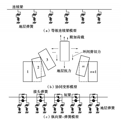
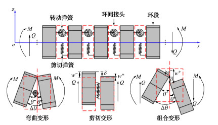
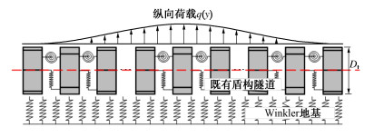
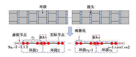
摘要: 为反映外荷载下盾构隧道相邻环间张开和错台,提出考虑环间接头影响的盾构隧道纵向变形简化解答。首先,引入纵向梁-弹簧模型模拟盾构隧道纵向受力变形,其中采用Timoshenko短梁考虑隧道环段变形,引入转动和剪切弹簧分别模拟环间接头转动与错台。其次,构建弹性地基上纵向梁-弹簧模型的有限差分方程,以解决环间接头-管环非连续变形求解问题,并推导外荷载下既有盾构隧道的纵向变形公式。最后,建立新建隧道上穿和下穿引起既有盾构隧道的纵向变形解答,并与新建隧道上、下穿越工程案例及现有理论方法对比验证。研究结果表明:所提方法预测的隧道位移与Timoshenko连续梁模型,协同变形模型和实测数据均具有较好的一致性,但所提方法得到的环间错台略低于Timoshenko梁模型和协同变形模型;所提方法可考虑环间接头的影响,得到的隧道位移曲线呈现既不光滑也不连续的特征,其中环段变形以刚体位移为主,而环间接头主要发生转动和错台;而基于现有理论所得盾构隧道纵向位移均为连续曲线,无法反映环间接头的真实转动与错台位移。Abstract: In order to reflect the opening and dislocation between adjacent rings of a shield tunnel subjected to external loads, an analytical solution for the longitudinal deformation of the shield tunnel is proposed which considering the effects of circumferential joints. Firstly, a simplified longitudinal beam-spring shield tunnel model is introduced to simulate the longitudinal deformation of the shield tunnel. The Timoshenko short beam is used to consider the deformation of the segmental ring. The rotation and shearing springs are used to simulate the rotation and dislocation of the circumferential joints, respectively. Secondly, the finite difference equation of the longitudinal beam-spring model resting on the elastic foundation is established to solve the discontinuous deformation of the circumferential joint-segmental ring. The formula for the longitudinal deformation of the existing shield tunnel under external loads is further derived. Finally, the solutions for the longitudinal deformation of the existing shield tunnel associated with overcrossing tunneling and undercrossing tunneling are established, respectively. The proposed method is verified with new tunnel over-crossing and under-crossing case histories and previous theoretical methods. The results show that the predicted results by the present solution are consistent with those by the Timoshenko continuous beam model and cooperative deformation model and the field measurements, but the dislocations obtained by the present solution are slightly lower than those by the Timoshenko continuous beam model and the cooperative deformation model. The proposed method takes the effects of the circumferential joints into consideration, and it leads to the predicted displacement curve of the tunnel, which is neither smooth nor continuous. It is found that the rigid displacement mainly occurs in the segmental rings, while the rotation and dislocation occur in the circumferential joints. The previous methods always give continuous displacement curves of tunnels, which cannot truly reflect the real rotation and dislocation of joints.
-
0. 引言
中国属多震国家,很多大型水利工程兴建在强震地区,在地震作用下,它们可能发生裂隙、下沉、坍塌甚至破坏,不仅将对工程本身造成损失,而且会带来巨大的次生灾害,后果十分严重,因此,有关地震方面的研究历来受到重视。
分析表明,目前研究地震破坏的方法大致可分为3类:一是数值模拟,其计算结果受计算参数和本构数学模型的影响很大;二是现场灾后调查,通过对地震现场破坏现象的调查,研究分析地震的破坏机理及抗震措施,由于实际地震的时空不确定性和复杂性,这类研究比较表观,不能重复,且无法取得地震全过程实测资料与数值分析结果进行相互验证;三是振动台试验方法,常规地面上的振动台模型试验由于无法模拟岩土材料的重力作用,因此多用于刚性材料的结构试验,而采用离心机振动台,则可以在原型应力条件下,在模型底部产生可控制的地震波,从而可以通过各种监测手段直接获得地震引起的岩土结构物的动力变形和稳定特性。因此土工离心机振动台被国内外岩土工程界认为是最有效的地震模拟试验手段,通过与数值模拟分析相互补充和验证,可以提高土工抗震研究水平,解决相关的岩土工程抗震问题[1-6]。
鉴于离心机振动台在抗震研究方面的突出优势,南京水利科学研究院在2002年自行研制了中国第一台NS-1型电液式土工离心机振动台[7],并利用该振动台研究了某混凝土面板堆石坝体的地震加速度反应特性、面板应变反应特性、坝体的变形特性等[4]。试验结果表明,该离心机振动台能满足岩土工程地震问题研究的要求,提供了一个非常有效的研究手段,可在工程实际中大力推广应用。
为了更好地满足科研和工程需要,南京水利科学研究院在此基础上研制了性能更可靠、技术指标更先进的NS-2型离心机振动台系统。本文主要介绍了该设备的设计关键技术和性能指标,给出其主要功能特点和技术参数。通过开展某沥青混凝土心墙砂砾石坝动态离心模型试验,初步验证了离心机振动台系统性能指标。
1. 离心机振动台系统概况
1.1 系统总体结构
NS-2型离心机振动台是由南京水利科学研究院和中国工程物理研究院联合研制,采用电液伺服液压驱动,实现水平单向振动(垂直于离心机转臂),如图1所示。主要由机械系统、液压系统、伺服控制系统、动态数据采集系统及离心模型试验辅助设备等组成,其中液压系统是系统的动力机构,机械系统提供负载运动支承以及试验体安放平台,伺服控制系统完成地震波形的模拟加载控制,系统组成如图2所示。
1.2 主要技术参数
根据离心机振动台模型试验研究的国内现状和所配置的土工离心机运行情况,同时考虑到土木和水利工程的实际情况,设计采用如下技术参数:
a)振动方向:一维水平振动(垂臂向);
b)驱动方式:液压(蓄能器)驱动;
c)最大振动加速度:amax=20g;最大速度:Vmax=0.5 m/s;最大振动幅值:Amax=5 mm;
d)最大振动时间:3 s
e)频率范围:20~200 Hz;
f)最大有效负载(含模型箱、模型、以及其它辅助装备):Mmax=500 kg;
g)振动台控制:利用以太网通过滑环实现通讯;
h)激振波形:地震波、随机波;
i)最大离心加速度:80g。
2. 主要部件的结构
2.1 机械系统
机械结构包括:滚柱导轨、振动台面、剪切模型箱、以及激振系统安装底板。
安装底板作为激振系统的安装基础,向下连接离心机吊篮、向上固定系统结构;滚柱导轨作为运动支承安装在底板上;振动台面通过滑块安装在滚柱导轨上,模型及模型箱作为振动负载安装在振动台面上。
2.2 液压系统
液压系统包括:伺服液压缸一套、蓄能器组一套、21 MPa油源、以及离心机上的供油系统等。
液压缸安装在吊篮底板中轴线上,背负一台MOOG电液伺服阀为液压缸供油;在吊篮内布置一组小容量蓄能器作为伺服阀的进、回油及供油稳压配套设备,在离心机大臂上布置一组大容量蓄能器作为激振系统主油路的供油设备,重新配置21 MPa油源。如图3所示。
2.3 伺服控制系统
伺服控制系统包括:伺服驱动系统、上位控制系统、数据测量采集系统。伺服驱动系统布置在离心机上仪器仓内,包括伺服驱动器、运动控制器以及配套的供电设备,实现伺服液压缸的位移跟随控制,具有预设凸轮曲线跟踪、自动调零、自动标定等功能;上位控制系统放置在实验控制间,安装有地震波形再现软件一套,实现地震波加速度振动波形的信号处理、地震波响应测量及控制,并具有试验数据和试验曲线的实时测量、屏显、存储、数据管理等功能,如图4;试验数据测量采集系统由传感器及信号采集设备组成,为伺服控制、安全保护、试验数据分析提供支持。
3. 性能评价
3.1 试验介绍
在南京水利科学研究院NHRI400 g·t大型土工离心机和NS-2型离心机振动台上开展某沥青混凝土心墙砂砾石坝的动态离心模型试验,限于篇幅,这里只介绍坝体模型试验的部分结果。振动台和离心机总体布置见图5。
从目前来看即使用世界最大的离心机要等比尺模拟全部的坝体仍然是不可能的,因此,本项研究采用不等比尺的离心模型试验方法,即模型几何比尺ηl小于加速度比尺的倒数1/ηg,振动台模型箱净尺寸为700 mm×350 mm×650 mm(长×宽×高)。模型设计时取大坝标准剖面,按平面问题进行试验。模拟范围:竖向从建基面2176 m高程到坝顶2304.5 m高程,即整个坝高128.50 m,顺河向取坝轴线上游160 m、下游155 m,共315 m宽。标准剖面的上游坝坡为1∶2.75~1∶2.25,下游坝坡为1∶1.8~1∶1.6;而模型模拟范围内上游坝坡为1∶2.75~1∶2.5,下游坝坡为1∶1.8~1∶1.7,不考虑马道和上坝公路,试验将上、下游坝坡简化成同一坡度,上游坝坡取1∶2.75,下游坝坡取1∶2.6。模型几何比尺ηl =1∶450,离心加速度比尺ηg =40。模型布置见图6。
本次试验输入波形为实际地震波,地震峰值加速度有2个:设计地震波516.5g(50 a超越概率2%场地波),对应无抗震措施模型M1和有抗震措施模型M3;校核地震波643.3g(100年超越概率2%场地波),对应无抗震措施模型M2和有抗震措施模型M4。模型试验所需筑坝材料取自现场,根据以往粒径效应研究成果,模型土料的限制粒径应小于土作用构件最小边长的1/15~1/30,原型砂砾石料的最大粒径为300 mm,离心振动台模型砂砾石料的限制粒径取为20 mm,存在一个对超粒径颗粒进行处理的问题。依据《水电水利工程粗粒土试验规程》DL/T5356—2006,把原级配缩制成试验级配最常用的有相似级配法和等量替代法。根据现场检测级配曲线,用相似级配法与等量替代法相结合的方法确定砂砾石料的试验级配,如图7所示,其不均匀系数和曲率系数与现场料相近。沥青砼心墙采用有机玻璃板模拟,心墙厚度按抗弯刚度相似条件确定;模型护坡采用1~2 mm厚的砼,由于厚度较薄,不会影响坝体的变形或破坏;有抗震措施是指在筑坝材料区域铺设土工格栅,土工格栅采用纱窗模拟,抗拉强度要求满足相似条件,为了模拟实际工程中筑坝材料嵌入格栅的情形,模型格栅在铺设前,需要在上下面各刷一层胶,使其能够粘合少量的堆石料,从而可以模拟筑坝材料嵌入格栅的效果。
为了量测坝体地震加速度反应,在坝轴线上沿高程2202.4,2224.8,2246.9,2269.8,2290.1 m共布置5个加速度计,同时在坝顶布置1个激光位移传感器,测试坝体地震震陷。
3.2 结果分析
以下给出的所有试验结果均已根据模型相似律换算至原型。
(1)无抗震措施模型试验
a)坝体加速度反应
图8和图9分别给出了模型M1和M2对应的建基面原型场地波和试验实际输入波时程线,前者目标波峰值分别为504.514g和-510.21g,输入波峰值分别是501.937g和-523.127g;后者目标波峰值分别为645.023g和-644.977g,输入波峰值分别是646.388g和-649.306g,从中可以看出,波形的频响特性较为吻合,试验输入波形较好地再现了目标场地波。
![]() 图 8 模型M1目标地震波和实际输入波时程曲线Figure 8. Time histories of target seismic waves and actual input waves for model M1
图 8 模型M1目标地震波和实际输入波时程曲线Figure 8. Time histories of target seismic waves and actual input waves for model M1![]() 图 9 模型M2目标地震波和实际输入波时程曲线Figure 9. Time histories of target seismic waves and actual input waves for model M2
图 9 模型M2目标地震波和实际输入波时程曲线Figure 9. Time histories of target seismic waves and actual input waves for model M2图10给出了无抗震措施情况下坝体在2种场地波条件下的最大加速度和放大系数随坝高的变化。
![]() 图 10 坝体坝轴线最大加速度和放大系数沿坝高分布Figure 10. Distribution of maximum acceleration and amplification coefficient of acceleration along dam height
图 10 坝体坝轴线最大加速度和放大系数沿坝高分布Figure 10. Distribution of maximum acceleration and amplification coefficient of acceleration along dam height由此可知:①在基岩输入地震加速度的作用下,坝体地震加速度反应随着高程的增加而相应增大,呈现出明显的放大效应;②坝体加速度反应随坝高的变化可以按约2/3坝高为界,大致分成两个线性变化段,上部的加速度放大效应强于下部;③随着基岩输入地震加速度的增加,坝体加速度放大系数总体上略有减小;④无抗震措施情况下坝体坝顶地震加速度放大系数约为2.7~3.0。
b)坝体破坏模式
图11和图12分别表示无抗震措施情况坝体在设计地震波作用下(M1)和校核地震波作用下(M2)的破坏情况。
从上述试验照片可以看出:①无抗震措施情况坝体在设计地震波条件下,下游未发现明显破坏,上游出现了一定程度的坝体破坏;在蓄水位处可见明显的护坡开裂;②无抗震措施情况坝体在校核地震波条件下,下游未发现明显破坏,上游出现了较大程度的坝体破坏;在蓄水位处和坝顶处均有明显的护坡开裂。
(2)有抗震措施模型试验
图13,14分别给出了2种场地波条件下有抗震措施和无抗震措施坝体的最大加速度和放大系数随坝高的变化。
![]() 图 13 设计地震波作用下坝轴线加速度及放大系数分布Figure 13. Distribution of acceleration and amplification coefficient of acceleration under design seismic waves
图 13 设计地震波作用下坝轴线加速度及放大系数分布Figure 13. Distribution of acceleration and amplification coefficient of acceleration under design seismic waves![]() 图 14 校核地震波作用下坝轴线加速度及放大系数分布Figure 14. Distribution of acceleration and amplification coefficient of acceleration under check seismic waves
图 14 校核地震波作用下坝轴线加速度及放大系数分布Figure 14. Distribution of acceleration and amplification coefficient of acceleration under check seismic waves由上述图中可以看出:①在基岩输入地震加速度的作用下,有抗震措施坝体地震加速度反应随着高程的增加而相应增大,呈现出明显的放大效应;②有抗震措施坝体加速度反应随坝高的变化可以按约2/3坝高为界,大致分成两个线性变化段,上部的加速度放大效应强于下部;③在抗震措施加固范围以下高程,有抗震措施和无抗震措施坝体的加速度放大效应大体一致;在抗震措施加固范围内,有抗震措施坝体的加速度放大效应略强于无抗震措施坝体;④有抗震措施坝体坝顶地震加速度放大系数约为3.0~3.4。
从试验结果分析可知,离心机振动台较好地再现了在地震作用下坝体内部加速度动态响应规律及坝体失稳破坏模式,为工程设计部门提供了参考依据,进一步验证了NS-2型离心机振动台设计性能指标完全满足工程科研需要。
4. 结论
(1)介绍南京水利科学研究院40 g·t离心机振动台设计关键技术和性能指标,主要包括机械系统、液压系统、伺服控制系统,可为土工离心机振动台建设和规划提供参考。
(2)NHRI-40 g·t离心机振动台的技术指标科学合理,设备的研制思路正确,波形控制系统可实现对目标波形的跟踪、调节和再现,目标波形和再现波形拟合度高;基于Labview编制的数据采集系统包括16个应变采集通道和24个电压采集通道,对试验数据进行实时测量、显示和存储。
(3)通过该离心机振动台测得国内某大坝的地震加速度响应分布表明,振动台的主要技术指标和性能达到了预期目的,完全能满足工程试验研究的需求。
-
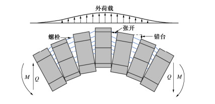
![]()
图 1 盾构隧道在外荷载下的纵向变形
Figure 1. Longitudinal deformations of a shield tunnel subjected to.external loads
![]()
图 4 在外荷载下盾构隧道纵向响应计算模型
Figure 4. Model for longitudinal responses of shield tunnel to external loads
![]()
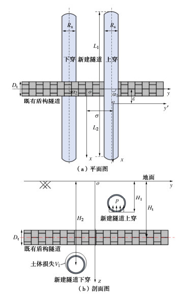
图 7 新建隧道上穿和下穿既有盾构隧道计算模型
Figure 7. Model for existing shield tunnel due to over-crossing tunneling and under-crossing tunneling
![]()
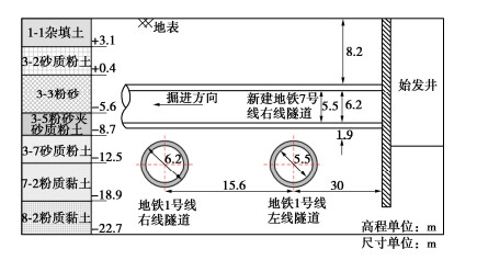
图 8 上穿工程剖面图
Figure 8. Sectional view of existing shield tunnel due to over-crossing tunneling
![]()
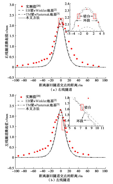
图 9 1号线双线隧道纵向位移实测值与计算值对比
Figure 9. Comparison between measured and computed displacements of tunnel of Metro Line 1
![]()
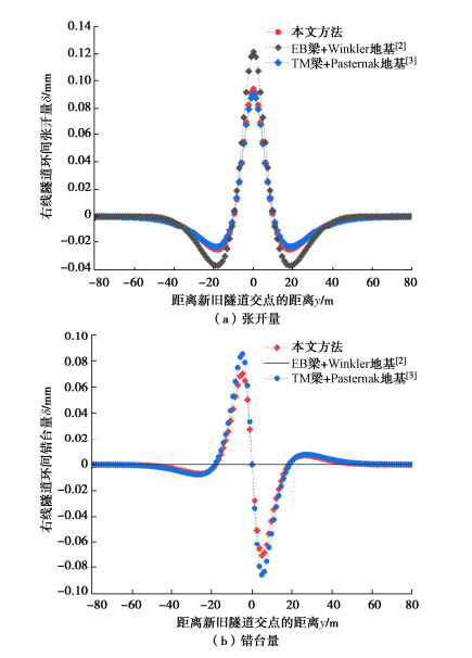
图 10 1号线右线隧道环间变形计算值对比
Figure 10. Comparison of calculated deformations of rings of right line tunnel of Metro Line 1
![]()
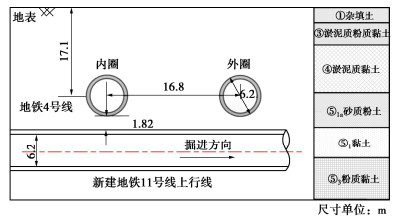
图 11 下穿工程剖面图
Figure 11. Sectional view of existing shield tunnel due to under-crossing tunneling
![]()
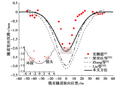
图 12 4号线内圈隧道竖向位移实测值与计算值对比
Figure 12. Comparison between measured and calculated vertical displacements of inner tunnel of Metro Line 4
![]()
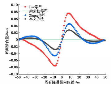
图 13 4号线内圈隧道环间错台量计算值对比
Figure 13. Comparison of calculated dislocations of rings of inner tunnel of Metro Line 4
![]()
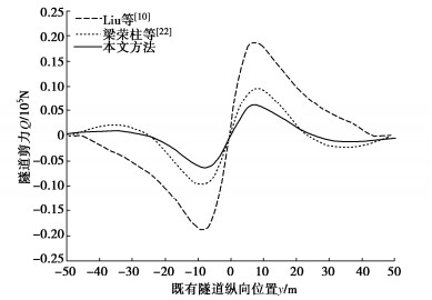
图 14 4号线内圈隧道剪力计算值对比
Figure 14. Comparison of calculated shearing forces of inner tunnel of Metro Line 4
表 1 既有盾构隧道结构参数
Table 1 Structural parameters of existing shield tunnel
管片弹性模量Ec/MPa 管片泊松比 环间螺栓数量nb 螺栓直径Db/mm 螺栓长度lb/mm 螺栓弹性模量Eb/MPa 3.45×10⁴ 0.2 17 30 400 2.06×10⁵  下载: 导出CSV
表 2 主要地层物理参数
Table 2 Physical parameters of main soil layers
土层 重度/(kN·m-3) 含水率/% 压缩模量Es0.1-0.2/MPa 泊松比 3-3粉砂 19.6 24.8 14.0 0.28 3-5粉砂夹粉质粉土 19.7 23.6 15.0 0.27 3-7砂质粉土 19.2 29.5 7.0 0.34 7-2粉质黏土 19.7 26.5 12.0 0.32
下载: 导出CSV
表 3 主要土层物理参数
Table 3 Physical parameters of main soil layers
土层 厚度/m 重度/(kN·m-3) 压缩模量Es0.1-0.2/MPa 泊松比 ④淤泥质黏土 8.4 16.7 2.09 0.33 ⑤1a砂质粉土 4.5 18.2 8.21 0.24 ⑤1黏土 4.3 17.8 3.36 0.26 ⑤3粉质黏土 5.8 18.1 4.66 0.29
下载: 导出CSV
-
[1] 张志伟, 梁荣柱, 李忠超, 等. 盾尾非对称推力作用下盾构隧道纵向变形分析[J]. 岩土力学, 2023, 44(1): 88-98. ZHANG Zhiwei, LIANG Rongzhu, LI Zhongchao, et al. Analysis of longitudinal deformation of shield tunnel subjected to shield tail asymmetric thrust[J]. Rock and Soil Mechanics, 2023, 44(1): 88-98. (in Chinese)
[2] LIANG R Z, XIA T D, HONG Y, et al. Effects of above-crossing tunnelling on the existing shield tunnels[J]. Tunnelling and Underground Space Technology, 2016, 58: 159-176. doi: 10.1016/j.tust.2016.05.002
[3] LIANG R Z, KANG C, XIANG L M, et al. Responses of in-service shield tunnel to overcrossing tunnelling in soft ground[J]. Environmental Earth Sciences, 2021, 80(5): 1-15.
[4] ZHANG Z G, HUANG M S. Geotechnical influence on existing subway tunnels induced by multiline tunneling in Shanghai soft soil[J]. Computers and Geotechnics, 2014, 56: 121-132. doi: 10.1016/j.compgeo.2013.11.008
[5] YU J, LI H, HUANG M S, et al. Timoshenko-beam-based response of existing tunnel to single tunneling underneath and numerical verification of opening and dislocation[J]. Computers and Geotechnics, 2022, 147: 104757. doi: 10.1016/j.compgeo.2022.104757
[6] 陈仁朋, 刘慕淳, 孟凡衍, 等. 基坑开挖旁侧盾构隧道结构横向受力与变形研究[J]. 岩土工程学报, 2023, 45(1): 24-32. doi: 10.11779/CJGE20211420 CHEN Renpeng, LIU Muchun, MENG Fanyan, et al. Circumferential forces and deformations of shield tunnels due to lateral excavation[J]. Chinese Journal of Geotechnical Engineering, 2023, 45(1): 24-32. (in Chinese) doi: 10.11779/CJGE20211420
[7] CHENG H Z, CHEN R P, WU H N, et al. A simplified method for estimating the longitudinal and circumferential behaviors of the shield-driven tunnel adjacent to a braced excavation[J]. Computers and Geotechnics, 2020, 123: 103595. doi: 10.1016/j.compgeo.2020.103595
[8] 魏新江, 洪文强, 魏纲, 等. 堆载引起临近地铁隧道的转动与错台变形计算[J]. 岩石力学与工程学报, 2018, 37(5): 1281-1289. WEI Xinjiang, HONG Wenqiang, WEI Gang, et al. Rotation and shearing dislocation deformation of subway tunnels due to adjacent ground stack load[J]. Chinese Journal of Rock Mechanics and Engineering, 2018, 37(5): 1281-1289. (in Chinese)
[9] LIU B, YU Z W, HAN Y H, et al. Analytical solution for the response of an existing tunnel induced by above-crossing shield tunneling[J]. Computers and Geotechnics, 2020, 124: 103624. doi: 10.1016/j.compgeo.2020.103624
[10] LIU B, YU Z W, ZHANG R H, et al. Effects of undercrossing tunneling on existing shield tunnels[J]. International Journal of Geomechanics, 2021, 21(8): 04021131. doi: 10.1061/(ASCE)GM.1943-5622.0002102
[11] 魏纲, 洪文强, 魏新江, 等. 基坑开挖引起邻近盾构隧道转动与错台变形计算[J]. 岩土工程学报, 2019, 41(7): 1251-1259. doi: 10.11779/CJGE201907009 WEI Gang, HONG Wenqiang, WEI Xinjiang, et al. Calculation of rigid body rotation and shearing dislocation deformation of adjacent shield tunnels due to excavation of foundation pits[J]. Chinese Journal of Geotechnical Engineering, 2019, 41(7): 1251-1259. (in Chinese) doi: 10.11779/CJGE201907009
[12] HUANG S F, CHEN Z B, XIE Y N, et al. A variational approach to the analysis of excavation-induced vertical deformation in a segmental tunnel[J]. Tunnelling and Underground Space Technology, 2022, 122: 104342. doi: 10.1016/j.tust.2021.104342
[13] 张治国, 程志翔, 张孟喜, 等. 考虑衬砌渗透性的盾构下穿既有隧道纵向结构错台变形研究[J]. 中国公路学报, 2022, 35(11): 180-194. ZHANG Zhiguo, CHENG Zhixiang, ZHANG Mengxi, et al. Dislocation deformation of existing longitudinal tunnel structure induced by shield tunneling by under-crossing considering influence of lining permeability[J]. China Journal of Highway and Transport, 2022, 35(11): 180-194. (in Chinese)
[14] KOIZUMI J, MURAKAMI H, SAINO K. Modelling of longitudinal structure of shield tunnel[J]. Journal of Japanese Society for Civil Engineering, 1988: 79-88. (in Japanese))
[15] HUANG W M, WANG J C, YANG Z X, et al. Analytical analysis of the longitudinal response of shield tunnel lining considering ring-to-ring interaction[J]. Computers and Geotechnics, 2022, 146: 104705. doi: 10.1016/j.compgeo.2022.104705
[16] KIENDL J, AURICCHIO F, HUGHES T J R, et al. Single-variable formulations and isogeometric discretizations for shear deformable beams[J]. Computer Methods in Applied Mechanics and Engineering, 2015, 284: 988-1004. doi: 10.1016/j.cma.2014.11.011
[17] WU H N, SHEN S L, LIAO S M, et al. Longitudinal structural modelling of shield tunnels considering shearing dislocation between segmental rings[J]. Tunnelling and Underground Space Technology, 2015, 50: 317-323. doi: 10.1016/j.tust.2015.08.001
[18] SHIBA Y, KAWASHIMA K, OBINATA N, et al. Evaluation procedure for seismic stress developed in shield tunnels based on seismic deformation method[J]. Doboku Gakkai Ronbunshu, 1989, 1989(404): 385-394. doi: 10.2208/jscej.1989.404_385
[19] LIANG R Z. Simplified analytical method for evaluating the effects of overcrossing tunnelling on existing shield tunnels using the nonlinear Pasternak foundation model[J]. Soils and Foundations, 2019, 59(6): 1711-1727.
[20] WU B, LIU W, SHI P, et al. A case study of newly tunnels over-crossing the existing subway tunnels[J]. International Journal of Distributed Sensor Networks, 2022, 18(3): 15501329221087183.
[21] 王如路, 袁强, 梁发云, 等. 道路填土引发软土地铁盾构隧道变形案例及整治技术[J]. 岩土工程学报, 2023, 45(1): 112-121. doi: 10.11779/CJGE20211459 WANG Rulu, YUAN Qiang, LIANG Fayun, et al. Case study and treatment technology for deformed shield tunnel in soft soils induced by road construction[J]. Chinese Journal of Geotechnical Engineering, 2023, 45(1): 112-121. (in Chinese) doi: 10.11779/CJGE20211459
[22] 梁荣柱, 宗梦繁, 康成, 等. 考虑隧道剪切效应的隧道下穿对既有盾构隧道的纵向影响[J]. 浙江大学学报(工学版), 2018, 52(3): 420-430, 472. LIANG Rongzhu, ZONG Mengfan, KANG Cheng, et al. Longitudinal impacts of existing shield tunnel due to down-crossing tunnelling considering shield tunnel shearing effect[J]. Journal of Zhejiang University (Engineering Science), 2018, 52(3): 420-430, 472. (in Chinese)
[23] SAGASETA C. Analysis of undraind soil deformation due to ground loss[J]. Géotechnique, 1987, 37(3): 301-320.
-
其他相关附件


计量
- 文章访问数: 0
- HTML全文浏览量: 0
- PDF下载量: 0
